Sylvac digital gages include calipers, micrometers, indicators, bore gages and a variety of hand and bench tools include a Bluetooth output option.
Connection of Sylvac instruments with Bluetooth output to a computer can be accomplished with three (3) different software modules (1 with 3 variants) offered by Sylvac.
- Sylvac Anywhere – Designed for use with tablets and mobile phones
- Sylcom – An actual data collection and SPC charting product.
- Vmux – Allows connection of up to 32 gages to a PC via a Bluetooth or cable.
- Vmux Lite – Available for 1 or 8 gages to a PC via a Bluetooth dongle
Both Vmux Lite versions allow transmitting data to the PC via Keyboard wedge, COM port emulation or direct to Excel.
Note: This document relates to the VMux Lite versions only. Version 1.47.4 is shown in the pictures in this document.
Vmux is offered at no charge and can be downloaded from the Sylvac website.
Download here: https://www.sylvac.ch/download-en/softwares/313-vmux-en
Bluetooth connection using Vmux requires Sylvac USB dongle, Pt #981.7100
Getting Started
- Download and install the Vmux software.
- Start the software and view the main screen. Click the Settings button to open up to full screen.
- Insert the dongle into a USB port and wait a few seconds. A message will appear stating “Dongle device detected”. (Note: this message will disappear after about 30 seconds)

Connecting the Gage
- Turn on the measuring tool and press the Mode button twice until
bt appears. Press the Set button until it displays On. Press the Mode button and the Bluetooth symbol will appear flashing in the upper right corner of the gage display. This indicates the gage is in pairing mode. - Press and hold the Mode button until
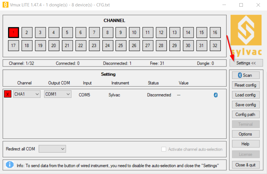
Unit appears, then release. Press the Mode button again and bt CFg will appear. Press the Set button until Simple appears. - The VMux software will begin scanning and the red buttons will turn green when connection is made as shown below. If they don’t click the Scan button on VMux to scan again.
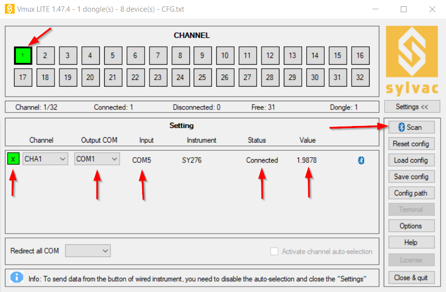
- Note that the line(s) in the table listing the gage(s) shows the channel number (if enabled), Output COM port, Input COM port, Status and Value.
These values are important to note: the Output COM port will be the port that this gage will send data to the PC on. Also, it will be the COM port specified in QC-Gage for this instrument. The status confirms the gage is connected and the Value will display the gage reading value in real-time which enables testing of the connection to the gage. The Input COM port is the COM port that the PC uses to connect to the dongle. If you add more gages, VMux will assign a different COM port to the Output port for each gage.
Note: the dropdown for Output allows selection of different COM ports if needed to avoid conflicts.
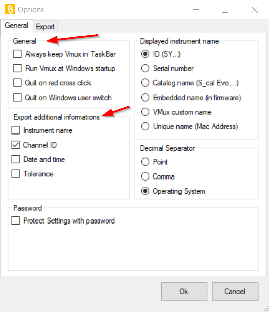
- There are several options available in the Vmux settings. If you click on the Options button along the right side, a window with two tabs will open. On the General Tab in the General section, you can choose how the software can be closed. With all items unchecked the only way to stop the software is to click the close and quit button on the main screen of VMux. If the red X is clicked with all General settings unchecked the software remains running and access to this screen is only accessible via the notification tray in the right portion of the Windows taskbar by double clicking the green Sylvac icon.
- The Export additional information section of this tab allows addition of information to the gage output as shown. Note that the channel ID is not configurable and always is in the form CHA#. For QC-Gage users a script has been created to extract the channel number from the string. This script is available by contacting support@prolinksoftware.com.
- Other settings on the general tab are self-explanatory.
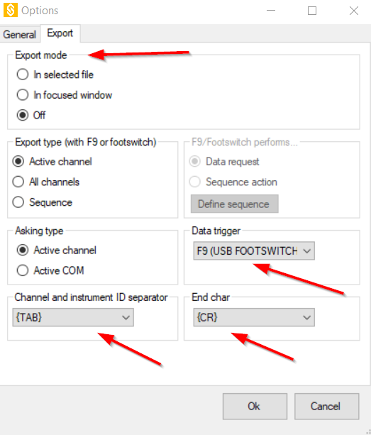
- The Export tab contains settings for enabling export to Excel, Trigger key for forced readings and determination of reading all or only active channels. Finally, it allows the separator and end characters to be set.
- Once the settings in VMux are complete you can close the screen by clicking the red X in the upper right of the screen. To insure that the software remains running, make sure the icon is visible in the notifications area of the Taskbar.
- Setup of the gage in QC-Gage is accomplished by setting up a gage in the Choose Gages section of the QC-Gage wizard or in the Global Gages section of QC-Gage. This setting is based on the output COM port associated with the gage in VMux screen.
- If the VMux software is not set to send a channel number the simple Raw Data script that is shipped with QC-Gage will be used. If the VMux is set to output the Channel number, you will need to contact Prolink support for a script file mentioned earlier that supports the output with channel number included in the data stream.
- Sending data from the Sylvac gage to QC-Gage is accomplished by pushing the Set button on the gage or pressing the F9 key on the computer keyboard. Optionally, you can configure the Get Command in the gage script to send a
?{Cr}. This will allow the use of the F12 key in the QC-Gage data entry screen as is displayed in that screen. This will allow the command to read the gage and to be consistent with other gages using the F12 key. See the QC-Gage manual for details on setting this up.
Note: On a PC with a fresh installation of VMux you can sometimes encounter a problem with the virtual COM ports not appearing in the PC device manager and not being active in the PC.
To fix: install a previous version of VMux from the link below and then install the latest version.
https://nc.sylvac.ch/s/bDCAWK9bjipPMtb