“My Gage seems to be working, but nothing is appearing in QC-Gage”.
There are a few reasons that a communication issue can occur between the software and the hardware. Typically, these boil down to: Hardware (Mechanical or Wiring), COM Port, or Spec Plan related issues.
Troubleshooting the Hardware
The first thing that needs to be done is to make sure that the hardware itself is not the root of the issue: Ensure that all wiring is correctly connected, and make sure if there is a “Read-Out” on the gage itself, that these numbers are “Human-Readable” (i.e. ASCII/Unicode). Once this is verified, we can move on to verifying the data is accepted by the computer.
Troubleshooting the Input via COM Port
In this step, we will be connecting the hardware to the computer via RS232/USB connectors. This step will require software called HyperTerminal – a lightweight program formerly bundled with Windows and used for controlling serial devices. You can download the software via the link here: http://www.prolinksoftware.com/download/article/HyperTerm.zip
Once this is downloaded, extract the zip file and run the application. Follow the steps below to begin troubleshooting your Gage:
- Have the gage manual handy for DIP switch and COM port settings.
- Connect the gage to the computer and note what COM port the gage is using.
- Start HyperTerminal from the location is was extracted to.
- Type a name (this information is up to you) for your HyperTerminal session.
- Select Connect Using and choose the COM Port (noted in Step 1) from the list.
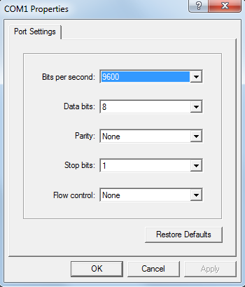
- Configure the COM port to match the settings for your particular gage.
- Click the OK button to connect to the gage.
- Click Connect (
 ) to open the COM Port.
- Take a few measurements with the gage. You should see data (readable characters) appear on the screen.
These readings should show up as “Human-readable” data; numbers that you can identify as your readings. If it does not come out in such a way, then the issue will be with the hardware. At this point, there will be nothing else we can do until the correct data can be input into HyperTerminal. If this is the case, please refer to your equipment’s manual, or contact the manufacturer directly.
If they are indeed coming through as human-readable, make note of the COM Port settings, and then we can move on to the next step.
Troubleshooting the Gage Definition
Reaching this step means that your gage is working entirely as it is intended, and that there is something going wrong within the software. The next step is to verify that the Gage Definition you currently have applied to your Spec Plan is capable of handing the data. The first step to this will be opening your Gage Definition outside of the Spec Plan.
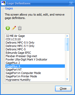
To access the Gage Definition, go to the Tools menu and select Gage Definitions. Find the definition that you have attached to the Spec Plan that is not correctly collecting the data. Once selected, select Edit ( ). Next, go to the Parser Instructions menu in the menu tree. The Advanced radio button should already be selected; you can go ahead and hit the Show Advanced button.
Figure 2: This menu grants you access to all of the pre-installed gage definitions, as well as any you have created or included in your Scripts folder.
Here, you will see the “Input Details – RS232” box; click the Properties button within this box, and ensure that the COM Port settings that were used to correctly receive the data into HyperTerminal are also applied here. Then do the following:
- Click the Open COM Port button (in the “Input Details – RS232” box).
- Click into the “Data received from the gage (or enter the expected values to test the parser)” input box
- Send a reading from your hardware. You should see something appear in this box if you have set everything up correctly.
- If there is data in the “Data received…” area, click the Start Parser button.
You should now see data in the Parse Variables section. You may only see a few of these boxes filled, but you should always see an Actual.
If everything is working as expected up until this point, we can move on to the next step.
Troubleshooting the Spec Plan
To ensure that everything is set correctly in your new spec plan, we’ll double-check a couple of place.
- Go to File > Edit > Choose your Spec Plan.
- Navigate to the Choose Gages area of the Spec Plan Editor.
- If you do not see the Gage Definition that was recently reviewed, please add it now by clicking the Add (
 ) button.
 - Next, navigate to the Features area of the Spec Plan Editor.
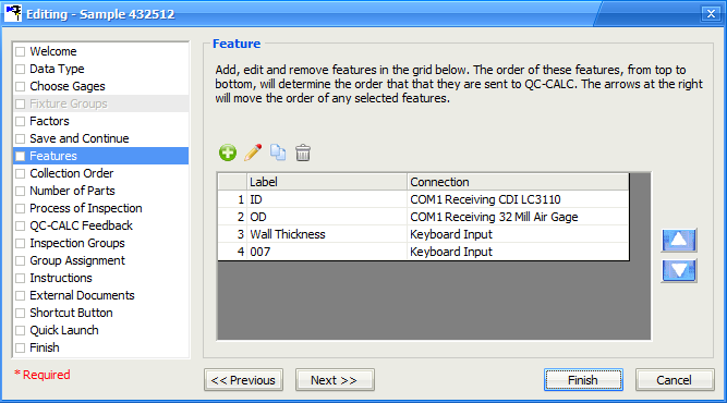
- You should see a list of all of the features that were created for the Spec Plan. This will include a column that identifies the Connection, or rather how each feature is accepting data. Make sure that these features are set to the correct connection type.
- If they are not set to the correct connection type, select the feature and click to Edit (
 ). You will see a Feature Source list here in this menu; select this to see all available gages (if you do not see the one you are looking for, please refer back to steps 2-3).
NOTE: If you are unaware of what certain settings do, it is generally best to leave them alone/disabled.
Still Stuck?
Occasionally things outside the guidance of this document can go wrong – and we’ll be happy to help. At this point it will be best to contact Prolink support with a detailed explanation of what the issue is. If you are enrolled in our Maintenance Program (more information: http://www.prolinksoftware.com/sales_maint.aspx), our support staff can be reached at (860) 659-5928 at extension #2 between 8 a.m. and 6 p.m. Eastern Standard. Otherwise, you can take advantage of our free support ticket system via the Support page of the website. Visit ProlinkSoftware.com/Support for further details.